ADF/NDB navigation is one of the oldest system aircraft pilots used in early aircraft during World War I and World War II. It was used for aviation or marine navigational aid earlier time. It used to be called Radio direction finder (RDF). In 1960s RDF had been developed and came up with a new name Automatic direction finder, or ADF. The ground station is called Non-directional (radio) beacon (NDB). And the Automatic Direction finder (ADF) is airborne equipment installed in the aircraft. The frequency range by ICAO is 190–1750 kHz ( LF/MF) but Universal use for NDB from 190KkHz to 535 kHz. And 535-1750khz is used for broadcasting Station E.g. AM radio Station.
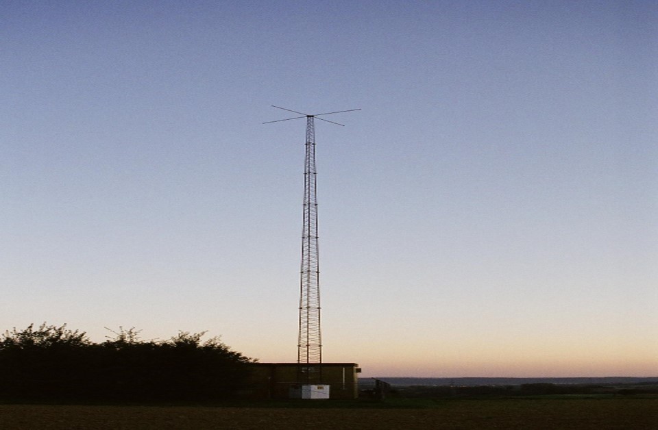
The ground-based, NDB station sends an omnidirectional signal to an aircraft and the ADF displays the position of the aircraft relative to NDB station. That is how a pilot can navigate towards the station using the NDB signal.
Classification of NDB
NDB station is classified into Four groups according to Ranges:
- Compass Locator – 15NM (used during approaches)
- Medium Homing (MH) – 25NM
- Homing (H) – 50NM
- High Homing (HH) – 75NM
Principle Of NDB & ADF
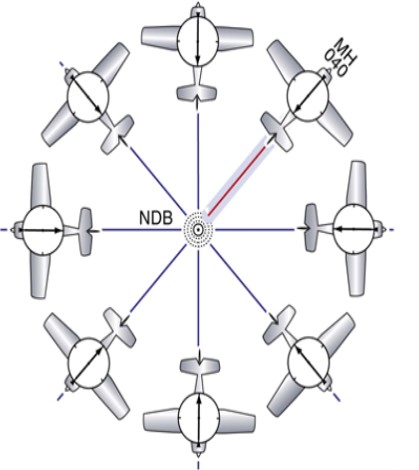
NDB station transmits constant signal/Omni-Directional Signal in all directions. The Signal does not provide Direction/Course guidance. And ADF display in the cockpit always keeps searching for the NDB signal. It provides bearing information on aircraft location to the airport
**Bearing is the angle between Aircraft nose clockwise to the station.
Airborne Equipment
ADF has 2 antennas installed in the aircraft.
- Directional/Loop Antenna- flat device containing loops of wires receiving radio signals accurately in one direction.
- Sense Antenna- non directional antenna receives signals in all direction.
ADF/NDB Limitations
- Electrical Interference effect caused by NDB due to cellphone, laptop, powerlines.
- Thunderstorm effect can lead the ADF needle points to the source of lightning flashes which is very dangerous for pilots to navigate towards an NDB station.
- Mountain/Terrain effect can occur due to mountains reflecting the radio waves.
- Night Effect/Ionosphere error happens just before sunrise and just after sunset, the NDB signals get refracted by the ionosphere leading to ADF needle fluctuations.
- Precipitation static happens when there is a building up of static charges on aircraft due to flying through rain, snow, or clouds. This kind of weather can interfere with ADF needle wandering.
- Coastal/Shoreline effects can degrade the accuracy of ADF.
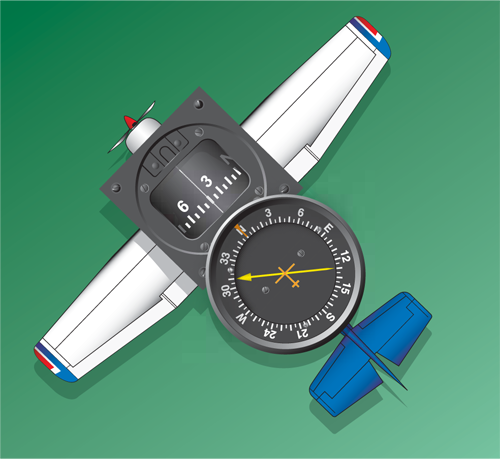
There are three types of Bearing indicator for ADF
- Fixed type
- Movable-card
- Radio magnetic indicator (RMI)

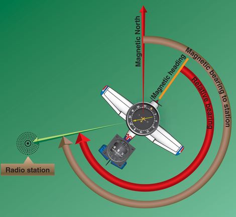
The terms below in the picture should be understood by each pilot to know how to use ADF for navigation.
- Magnetic heading (MH) – Compass direction/ Nose of the Aircraft
- Relative bearing (RB)– Angle between Nose of the A/c to the tip of the Pointer/Station.
- Magnetic bearing (MB)– Angle between MN to the tip of the Pointer/station
These are the basic learning of ADF navigation system. To understand better how ADF works, I would like to share a link below to see it’s operation.
Click here to visualize ADF Operation!